We install a lot of solar and home battery systems and many customers ask us to install an electric vehicle (EV) charge point at the same time. It’s a natural fit, of course, as it’s well known that many people will install solar then later buy an EV. The opposite is also true, with EV drivers seven times more likely to have solar panels.
We have blogged extensively in the past on solar charging, and in particular using a Zappi charge point. It is manufactured by myEnergi, a British company, and is the market leading charge point for diverting excess solar power to an EV for free charging.
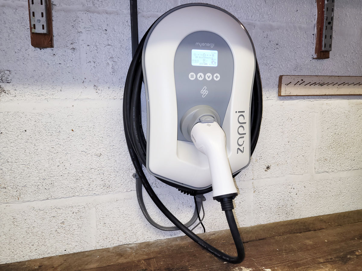
myEnergi Zappi EV Charge Point (Image: T. Larkum/Tanjent)
Installation
Mounting
The Zappi arrives in a large cardboard box along with its charge cable and grid sensor. Cleverly, part of the box can be removed to use as a template for marking out the positions of the mounting holes. Typically three holes are used – one at the top, and others bottom left and bottom right (however, central holes can be used if fitting to a post).
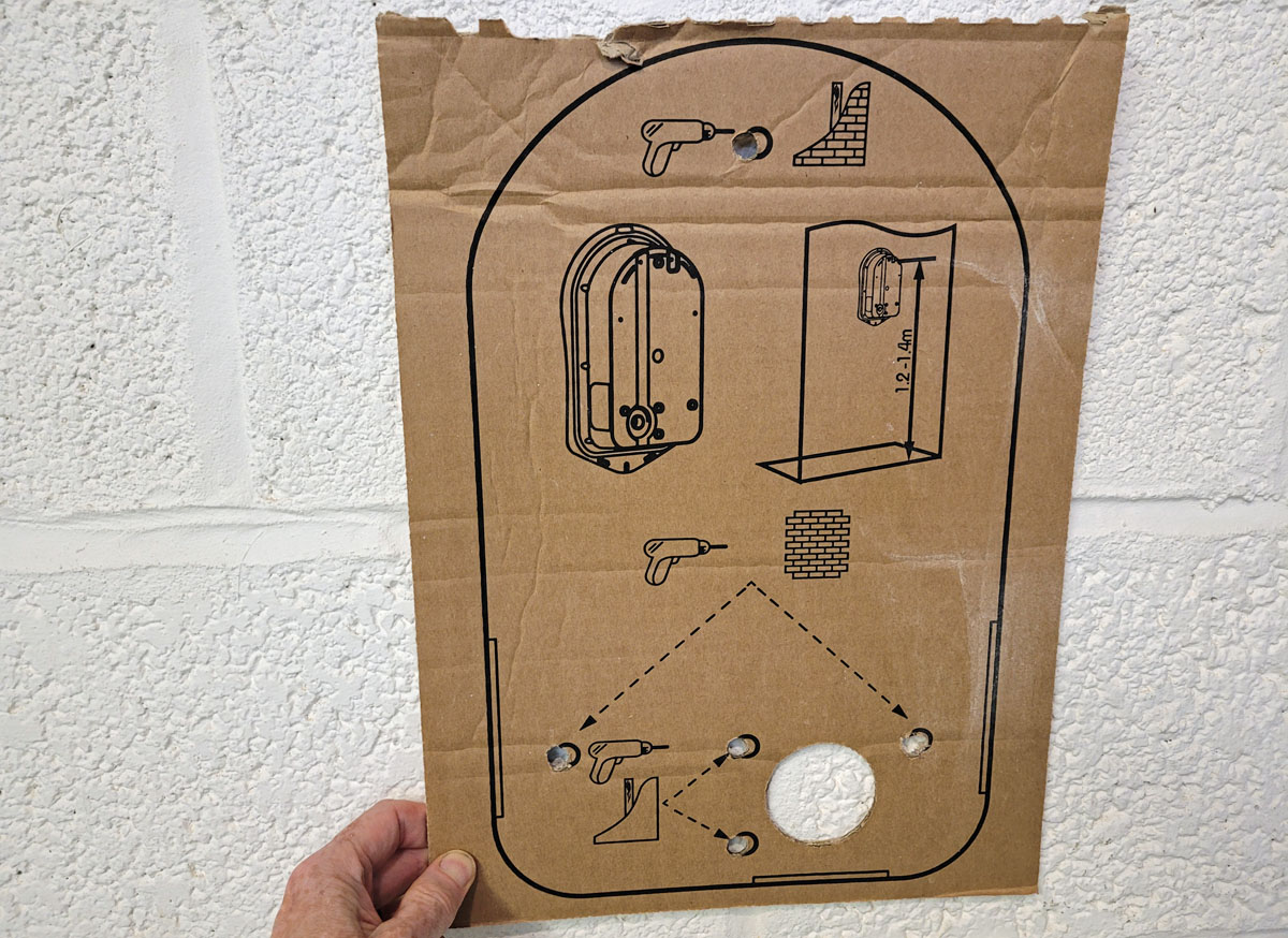
Zappi cardboard template (Image: T. Larkum/Tanjent)
Having marked and drilled these holes, the next step is to mount the Zappi on the wall – first it is necessary to remove the coloured fascia (which unclips at the bottom), then unscrew the Zappi front plate (noting the screws are captive, so don’t unscrew them so far they fall out), then unplug the ribbon cable that goes from the body to the front plate. At this point the Zappi body can be screwed to the wall.
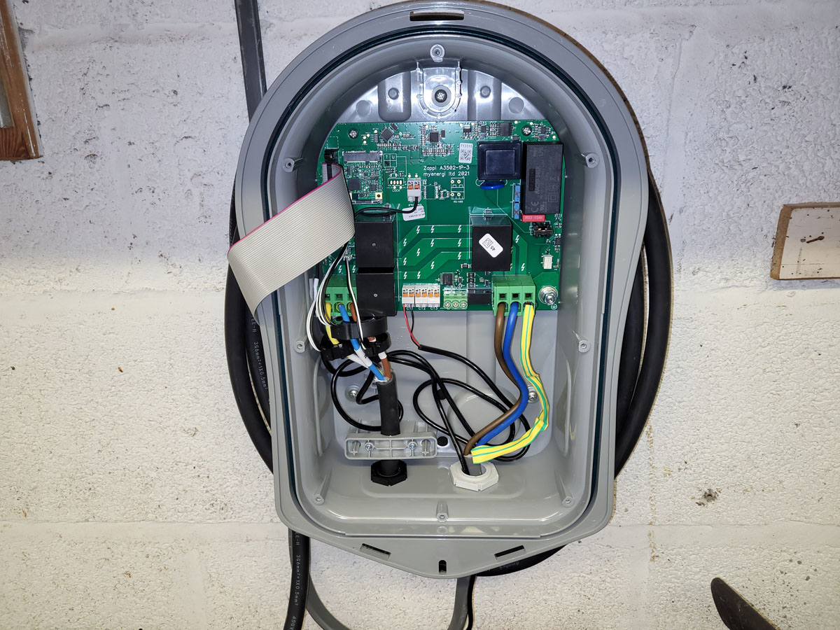
Zappi mounted on wall, faceplate off (Image: T. Larkum/Tanjent)
Since 30 December 2022 newly installed EV charge points have been required to have a tamper-proof protection system. Most new Zappis come with this as a small extra circuit board already installed; however those built before this date but installed after it will need the board fitting retrospectively by a competent person. It is straightforward to install as it just clips onto the top of the circuit board on the back of the face plate.
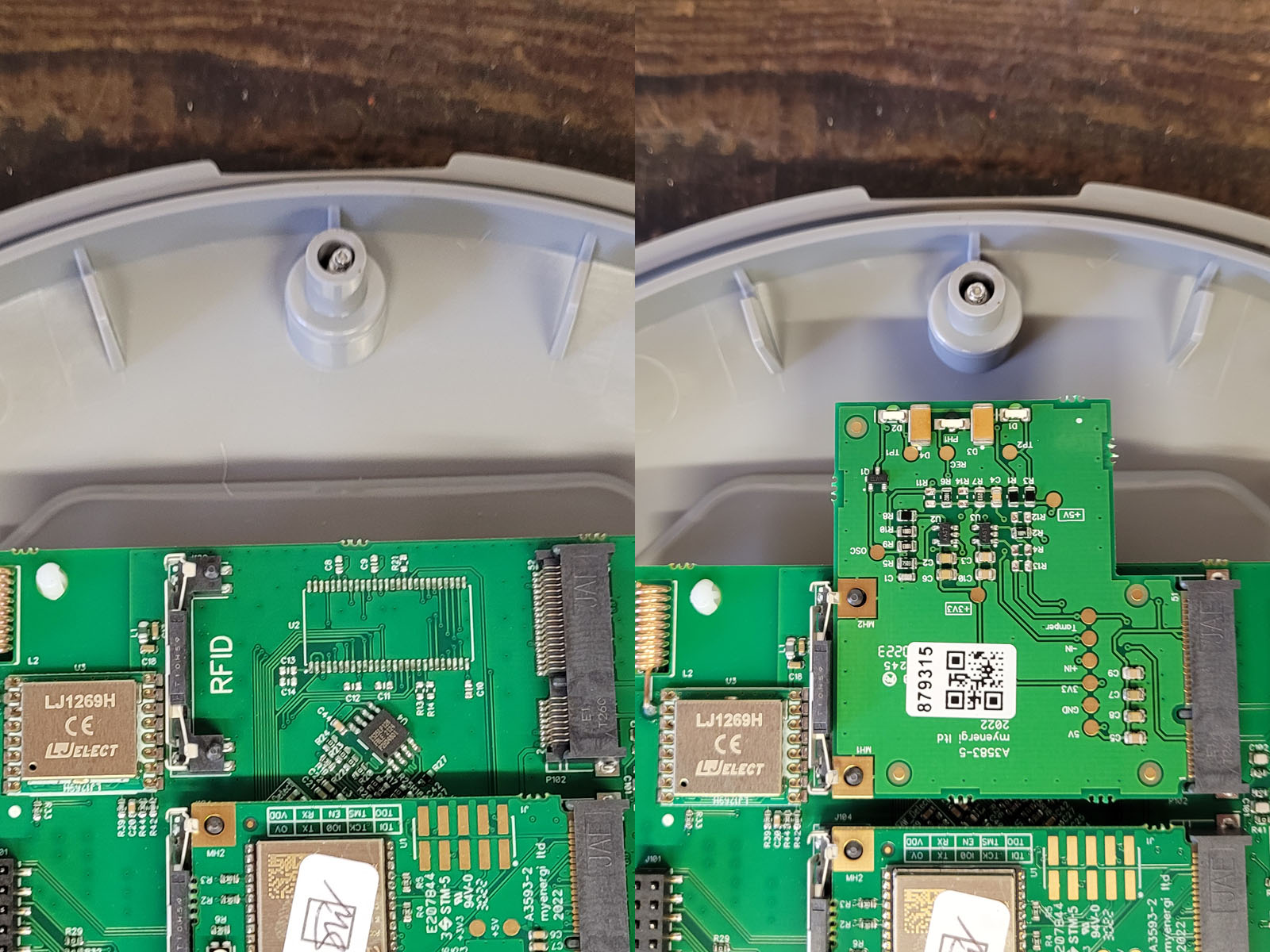
Zappi tamper board, before and after fitting (Image: T. Larkum/Tanjent)
Electrics
Once the Zappi is on the wall it’s time to run a power cable to it. Exactly how this is configured will depend on many factors such as the arrangement of the house electrics, the distance to travel (which will determine cable size) and so on. A typical arrangement is that the charge point will be connected into its own consumer board rather than go into an existing consumer board. This is because it is high power and its breaker can typically run hot, and therefore shouldn’t be squeezed in between other breakers as it may cause them to trip accidentally. The new consumer board will usually be powered from a Henley block, a splitter on the incoming grid feed.
The electrician who does the install will design and specify the appropriate electrical arrangement. He will also make every effort to provide a neat run of cable from the consumer board to the charge point, for example through a loft space, a void, a cavity wall or, where appropriate, along the bottom of an outside wall or fence.
The example below is in a garage. The grid connection comes in from the meter outside through the wall at A. It is split at a Henley block at B into the existing consumer units, and now also to the new consumer unit at C. Power then goes up into the loft space at D, back down at E, and into the underside of the Zappi at F.
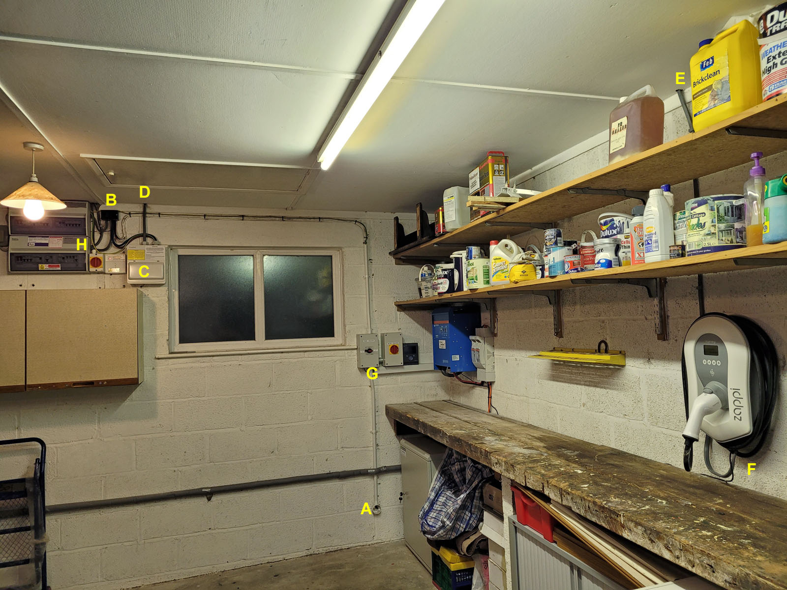
Zappi cable run (Image: T. Larkum/Tanjent)
The grid supply wires go into clamp terminals at the bottom of the main circuit board in the Zappi body; if the Zappi is installed outside this cable must pass through a waterproof gland.
Sensors
As well as power, the Zappi needs sensor connections; these are current transformer (CT) clamps that measure the current in a cable. The myEnergi clamps come with 5m of cable; for longer distances a wireless extender known as a Harvi can be used.
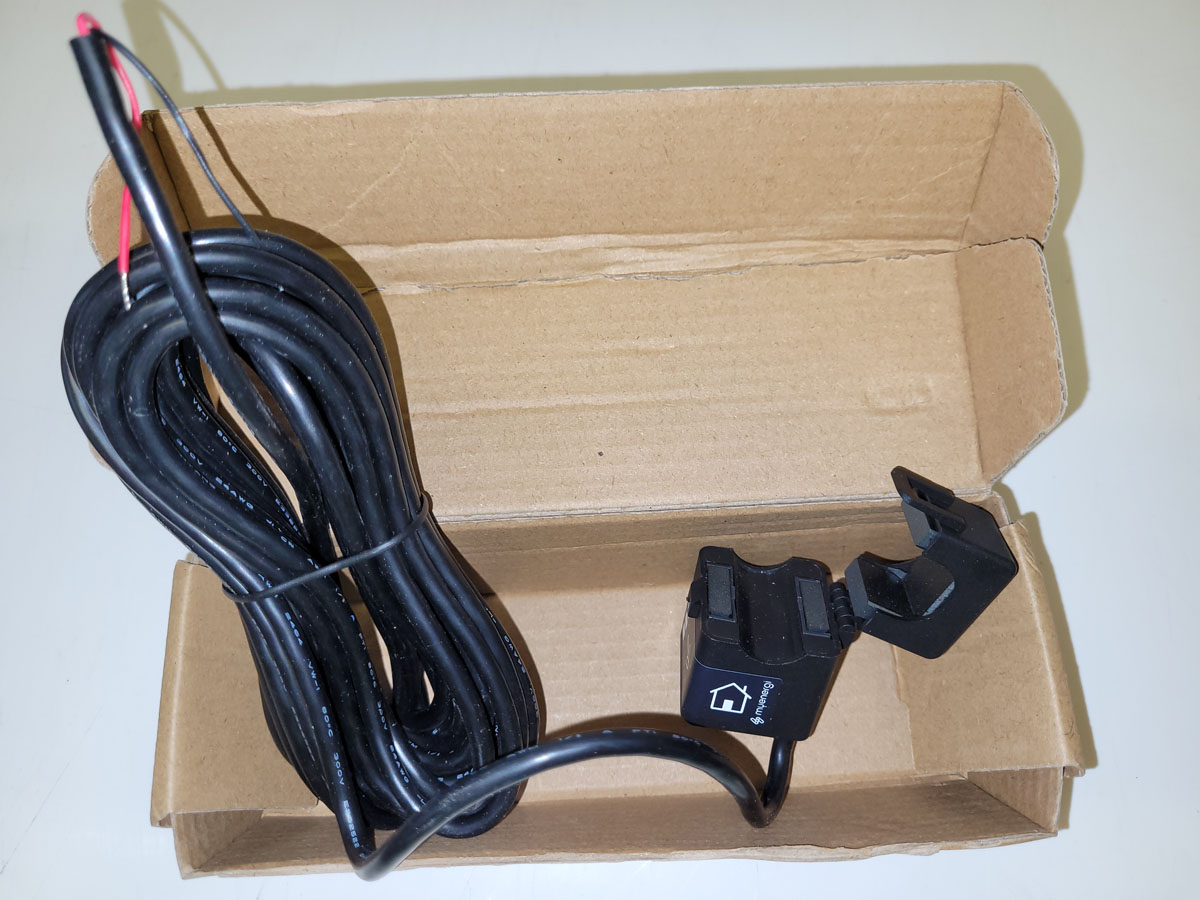
myEnergi CT clamp (Image: T. Larkum/Tanjent)
For a typical single phase install the sensors are configured as follows:
- Grid connection: This measures how much electricity is flowing in and out of the grid supply and is fitted around the ‘line’ (previously referred to as ‘live’) cable of the mains (its location is marked G in the example above). Primarily it is looking for electricity leaving the property, i.e. excess solar generation, so it can be automatically diverted to the car. It is mandatory for the Zappi to work correctly, and is usually connected in the Zappi to the ‘CT1’ terminals.
- Solar connection: This measures how much solar power is being generated and is fitted around the line cable from the solar inverter to the consumer unit (its location is marked H in the example above). It is optional, and is usually connected to the ‘CT2’ terminals. If available the solar power is shown in real-time on the Zappi screen, but the Zappi can work without it.
- Battery connection: This measures how much power is being provided by a home battery system if there is one, and is fitted around the line cable from the battery inverter to the consumer unit (it is not visible in the example above). It is optional, and is usually connected to the ‘CT3’ terminals. If available, it provides an option through the Zappi settings to prevent the Zappi from accidentally emptying the battery (the charge is reduced to only match what is spare from the solar, without dipping into the battery).
At this point the physical installation of the Zappi is complete and it can be powered up.